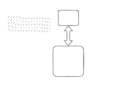
What is the Matrix?
first steps and thoughts
I am playing and experimenting with guitar pedals since I started to play the bass. When I started this research, which I called “double bass and effects” at first, I used my (existing) pedalboard and extended it with a two looper style pedals. (TC electronic DITTO and Red Panda Labs – TENSOR). I split the signal before the pedals because I wanted to have independent layers.
This is the very fist morning jam I did with this setup:

I continued to play around with this kind of setup. There are more morning jams with this setup:
2nd morning jam – atmospheric layers
This morning jam was right before I started to experiment with ableton:
4th morning jam – more atmo
“a journey to”
With this setup I recorded a track with the “Arthur Possing Quartett” at the world famous Real World Studios in England:
Signal flow:
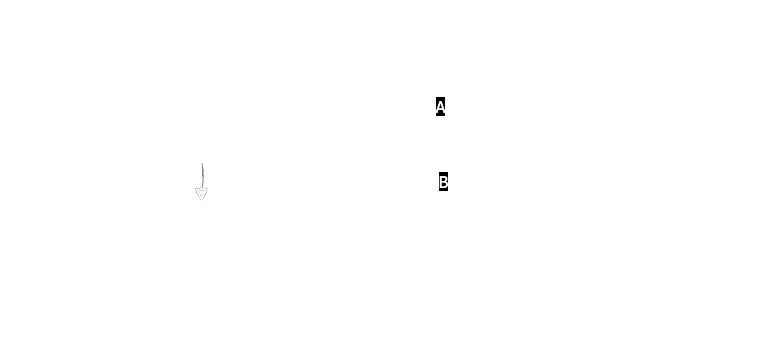
Although this signal chain might look complex, it is pretty simple though. After the delay (Strymon) I split the signal once. This is the “always on” signal. (Also called dry signal) The TENSOR had a “kill dry” active, that means, only recorded audio (by this looper pedal) is audible. When it is not engaged, no signal comes through. With this setup I could build three independent layers:
- Atmospheric layer with the tensor,
- Switch to path (B) and add another texture layer with the “supa puss” and 856.
- Switch back to (A). The tensor and 856 continued to play, but no signal from my playing was coming through those two paths. Instead only the dry signal with fuzz, overdrive and delay was audible.
After this memorable recording session experience, I intensified my experiments with ABLETON LIVE and looping techniques and my research question became more and more clear. I wanted to explore not only the possibilities to use ABLETON LIVE as a perfect looping machine, I also wanted to explore the possibilities of sound manipulation with pedals.
My resources in regards to signal routing were quite limited, my audio interface at that time had four inputs and four outputs. Basically I could put all pedals in a serial chain. But, if I wanted to change the order of effects or add another pedal into the chain, I had to unplug and reconnect them, which takes time. That is perfectly fine in a studio recording context, where you have the opportunity and time. But this is not adequate for a live performance, when you would like to use more than only one setting.
more pedals
It is indeed a kind of philosophy how many pedals to use and which order to put them. In the beginning of 2021, I purchased a bunch of new pedals, all of which I wanted to integrate in my setup. 11 in total. I was longing for a setup where I could effortlessly and quickly change both: Order and parallel processing. even feedback loops.
To be perfect, it would be possible to control the signal flow digitally or via MIDI.
I knew that there were no solutions for such a task existent. At least, at that time.
existent hardware solutions
MATRISE
A pedal company from Norway, PLADASK ELEKTRISK had a very interesting device. A 4×4 analog matrix mixer. It is called “MATRISE” and looks like this:

With this unit you could connect 3 pedals and send anything anywhere and you have the option to flip the phase.
PRO:
- pure analog signal flow (means no latency because of AD conversion)
- tactile → the magic of twisting knobs
CONS:
- it is a “only” 4×4 matrix. 1×1 is needed for in and out. 3 pedals only. MONO, of course. (I have 6 stereo pedals….)
- Most of the time it is not available. It is a small company with limited resources.
- no possibility of control via MIDI or any other computer signal.
Patchulator by bored brain
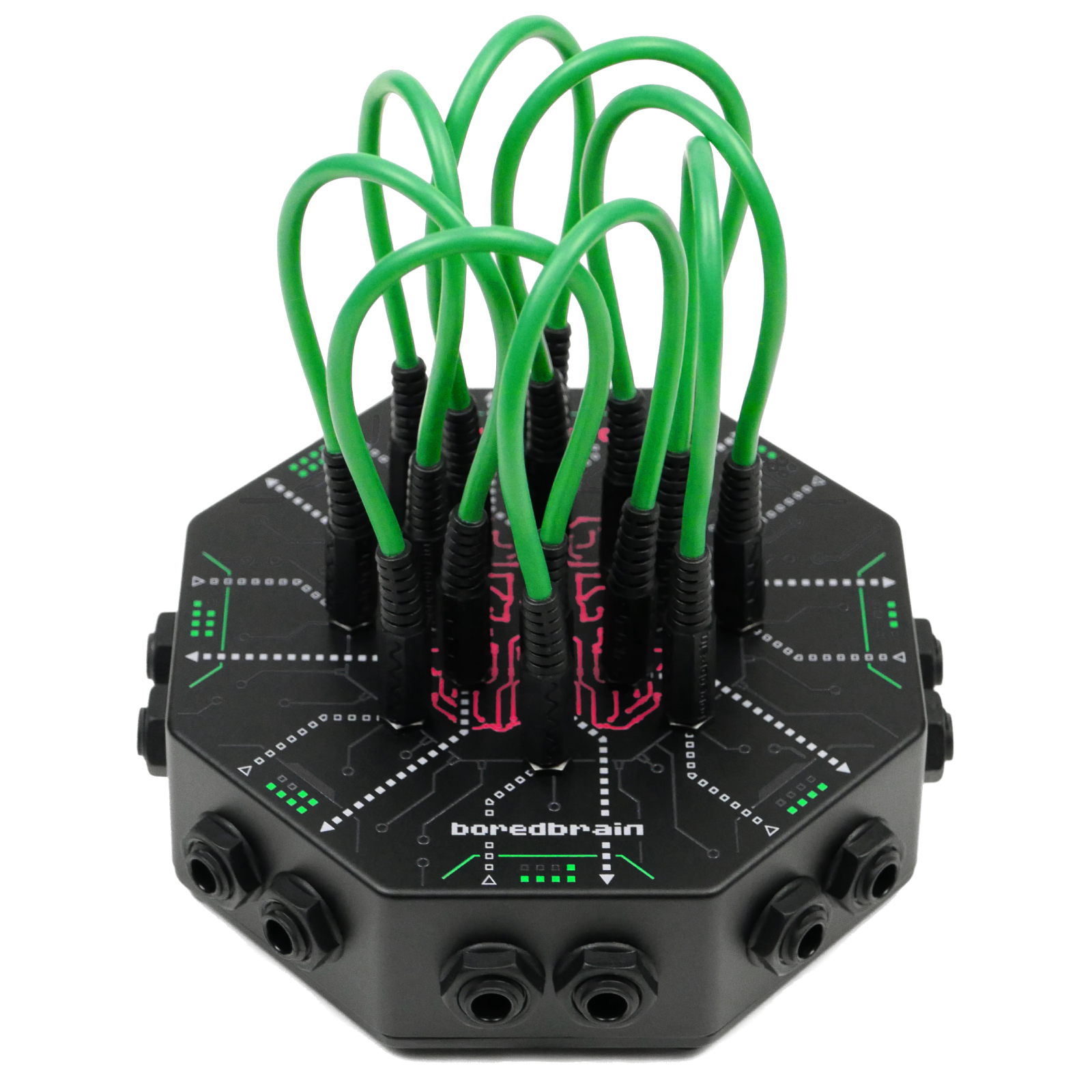
Another piece of gear I found was the Patchulator by bored brain, a 8×8 patch matrix:
It’s not really a matrix mixer, more a reorder tool. You can send one output only to one other input. Perfect for quickly re-ordering pedals.
PROS:
- relatively cheap (129$)
- 8 ins and outs
- Small and passive operation
CONS:
- no remote switch possibility
- no control over volume being sent
Matrix Mixer by erica synths
This unit just came out recently(summer 2021), when I had my custom solution already finished. It a 16×16 matrix mixer, main inputs and outputs are separate and is midi controllable. It comes from the eurorack world (modular synthesisers)

PROS:
- 16×16! (as most of my pedals are stereo that would be not enough….)
- midi controllable
CONS:
- all connectors are mini-jack, that would mean the need of 32 adapter cables….
- No stereo pairing
- it was too late anyway……
Although this piece of gear would fit most of my needs, I am glad I found another solution…..
using ableton as a mixer matrix
After it became clear to me, that there is no easy hardware solution I though about possible software based solutions. There is ABLETON LIVE and I already used it for my scripted looping.
I purchased a used audio interface (Saffire Pro 40) and a 8-channel DAAD converter, so I had 16 inputs and output in total. I connected all of my pedals in a separate inputs and outputs. Inside of ableton I had an individual audio track(input) and a send track(output) for each pedal.
With the software monitoring activated I was could now send any signal to any pedal.
I used a Behringer BCF 2000 to control the volumes, but it was confusing, hard to control and stay on top of things. And then there were other problems too:
latency and CPU overload
This solution over ABLETON LIVE had one major problem. If I go through the audio engine of ABLETON, there will be noticeable latency. About 14ms minimum. This adds up each time I go from one pedal to the other. e.g. Going only through two pedals adds up to 84ms.
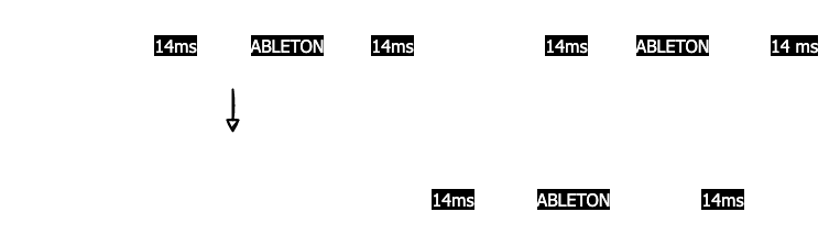
Latencies greater than 15ms are noticeable for listeners (link), especially when you are the player (and listener). Some colleagues of mine are sensitive to latency greater then 6ms.
(A short article about audio latency on wikipedia is here
But the latency was not even the real problem. With each audio input monitoring activated it put a serious amount of work to the CPU, which resulted in permanent CPU overloads and audio dropouts.
Direct Monitoring and a possible path to a solution
Of course, the problem of latency is not new to the world of audio recording and processing. There is a technology called “Direct Monitoring”, which is a shortcut on the signal path before any DAW processing in the computer directly inside the interface. On some audio interfaces it is done by an analog signal path fed directly back to the monitor / phones output. No latency, no CPU strain.
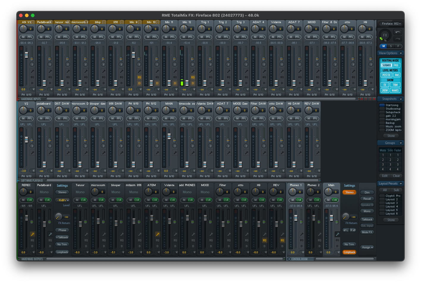
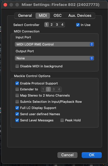
I finally a closer look at RME interfaces, which have a stellar reputation in regards to reliability and quality. It comes with a mixer software, called TotalMIX, which is packed with features. It claimed that it could be controlled remotely via MIDI.
I was intrigued and after some more research I bought a RME Fireface 802 and another DAAD converter additional to the one I had.
I had now 30 analog inputs and outputs, plus a “zero latency”(*)1 mixing software, fully controllable via MIDI.
Programming of the matrix
Two questions arose:
- How do I implement the operation on a piece of hardware?
- How do I manage and implement the control on the backend?
1. Hardware controller for the matrix
I had a Novation Launchpad mini mk1 available. It is a hardware controller with a 8×8 pad surface. My first version was straight forward, each row represents an output (or a destination) and each column represents an input (source).
E.g. To send input 4(856zellersasn) to destination 6(Hologram), I would press button 20. The LED of the button would light up and to clear this route, I would simply press it again. (This is also called “toggle” behaviour of a button). The upside of this solution was that I have a direct visualisation of what is going where.
But it turned out to be much more complicated to realise. With a 8×8 matrix I am limited to 7 effect chains, 1 is for a representation as an input. But I was planning with 11 effect chains. The output would have been elegantly represented by the middle buttons where source and destination meet.
It was also not possible to get the launchpad(mk1) in a simple note-toggle-behaviour. Nor could I get the visual feedback to work. I got a mk3 later where it was not problem, but at that time I already advanced to another concept.
SOURCE – DESTINATION buttons
For a 12×12 matrix I would need another hardware controller. With at least 12×12 buttons. (That is obvious, no?) I did research and found possible controller, although they were boutique or custom made. Therefor very expensive and unsure on the software functionality.
(Example: pic, price etc)
After some re-thinking I came up with a possible solution. I use 1 button for each source and one 1 button representing each possible destination. For 11 effects(in & outs) and 1 input and 1 output this would be 24 buttons total. This fits into three rows on a launchpad:
To assign a route, I press and hold down the desired destination and press a source to turn on the connection. Although I have future plans to add features, this concept turned out to be very effective, intuitive and relatively easy to implement, thanks to the architecture of RME Totalmix.
2. Implementation of the backend, RME Totalmix
[RME Total MIX][totalmix] is controllable via MIDI they said. But there was a learning curve to understand how to do this. There was a dedicated “MATRIX VIEW” inside the software:
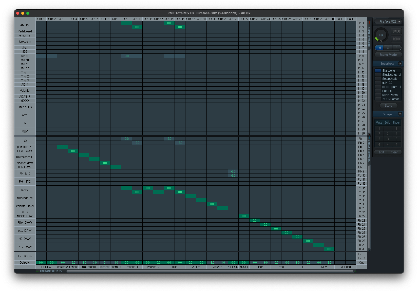
I first thought there is a dedicated midi command for each cell, but after some trial and error, I found out that it worked differently. I finally read the manual, but the description was rather thrifty:
Furthermore all faders of all three rows can be controlled via simple Control Change commands. The format for the Control Change commands is:
Bx yy zz
x = MIDI channel
yy = control number zz = value
The first row in TotalMix is addressed by MIDI channels 1 up to 4, the middle row by channels 5 up to 8 and the bottom row by channels 9 up to 12.
16 Controller numbers are used: 102 up to 117 (= hex 66 to 75). With these 16 Controllers (= faders) and 4 MIDI channels each per row, up to 64 faders can be controlled per row (as required by the HDSPe MADI).
It took many hours of research to find out and understand how [RME Total MIX][totalmix] is designed. It is designed to work with all the audio interfaces of the RME product line. Each of them has a different number of inputs and outputs. Because of that, the MIDI implementation is always RELATIVE to the interface used.
The basic functionality of [RME Total MIX][totalmix]
I think it would be helpful to explain the basic concept of Totalmix first, although I won’t go into details too deep. In the mixer view there are three rows representing:
- Hardware inputs
- Software outputs
- Hardware outputs
You select an output in the bottom row (hardware outputs), and row 1&2 will change corresponding to the mix settings for the selected output. To change the mix for another output, you have to select the output on the bottom row. This selection is also called submix. On the right there are dedicated submixes for Phones 1,2 and a master.
There are 2 types of MIDI commands for controlling the faders:
- A dedicated MIDI CC message to control the volume of each fader in the first row:
Back to the manual:
The first row is addressed by MIDI channels 1 up to 4, Controller numbers used: 102 up to 117
To control the first fader on the upper left I send a MIDI CC Nr 102 command
on channel 1, the second fader is Channel 1, CC 103, etc….
- A CC MIDI message to select a submix.
Back to the manual:Select submix (fader) in third row: – channel 1/2: BC 68/69 xx
channel 3/4: BC 6A/6B xx
It took another while to find out, how I could use this information. These values are in HEX(numbering on the base of 16). This is often preferred by programmers. Unfortunately, this manual was written by programmers and is therefore not easy to understand for an average musician. I have a history and interest in programming, but even for me, this was not obvious.
BC is 13 in the decimal system. And 68(HEX) is 104. To select Submix 1 (first channel in the third row) I send a MIDI CC nr. 104 on channel 13. For submix 2, MIDI CC nr. 105 on channel 13. And so on.
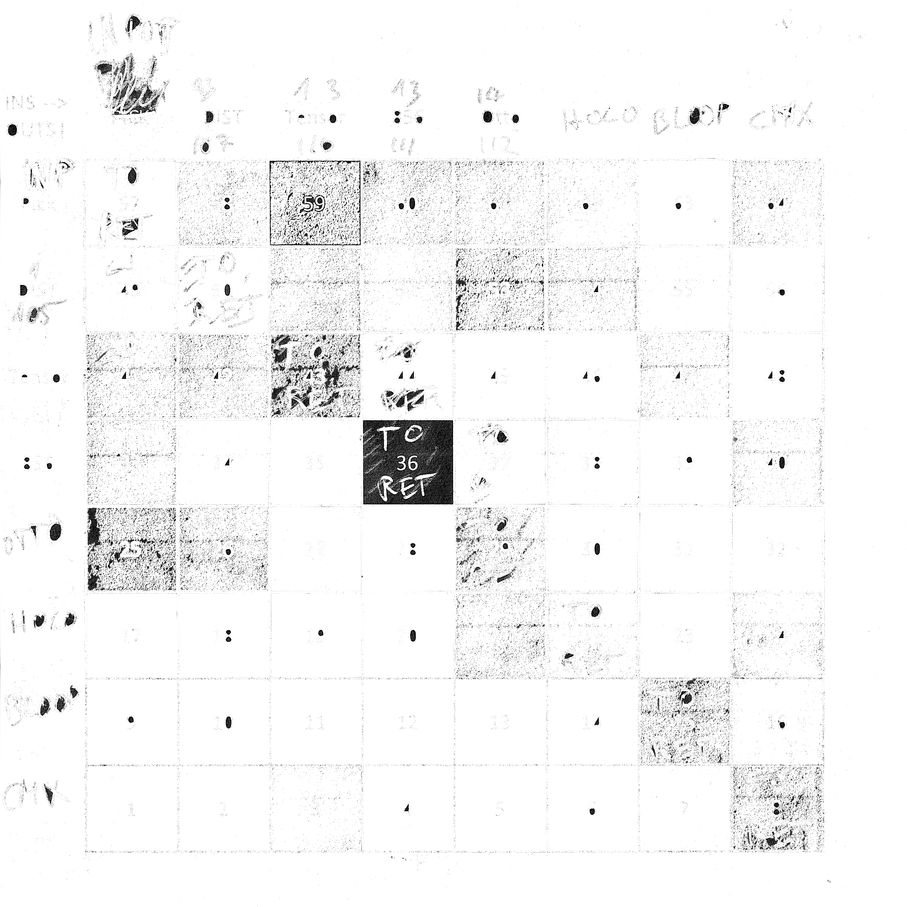
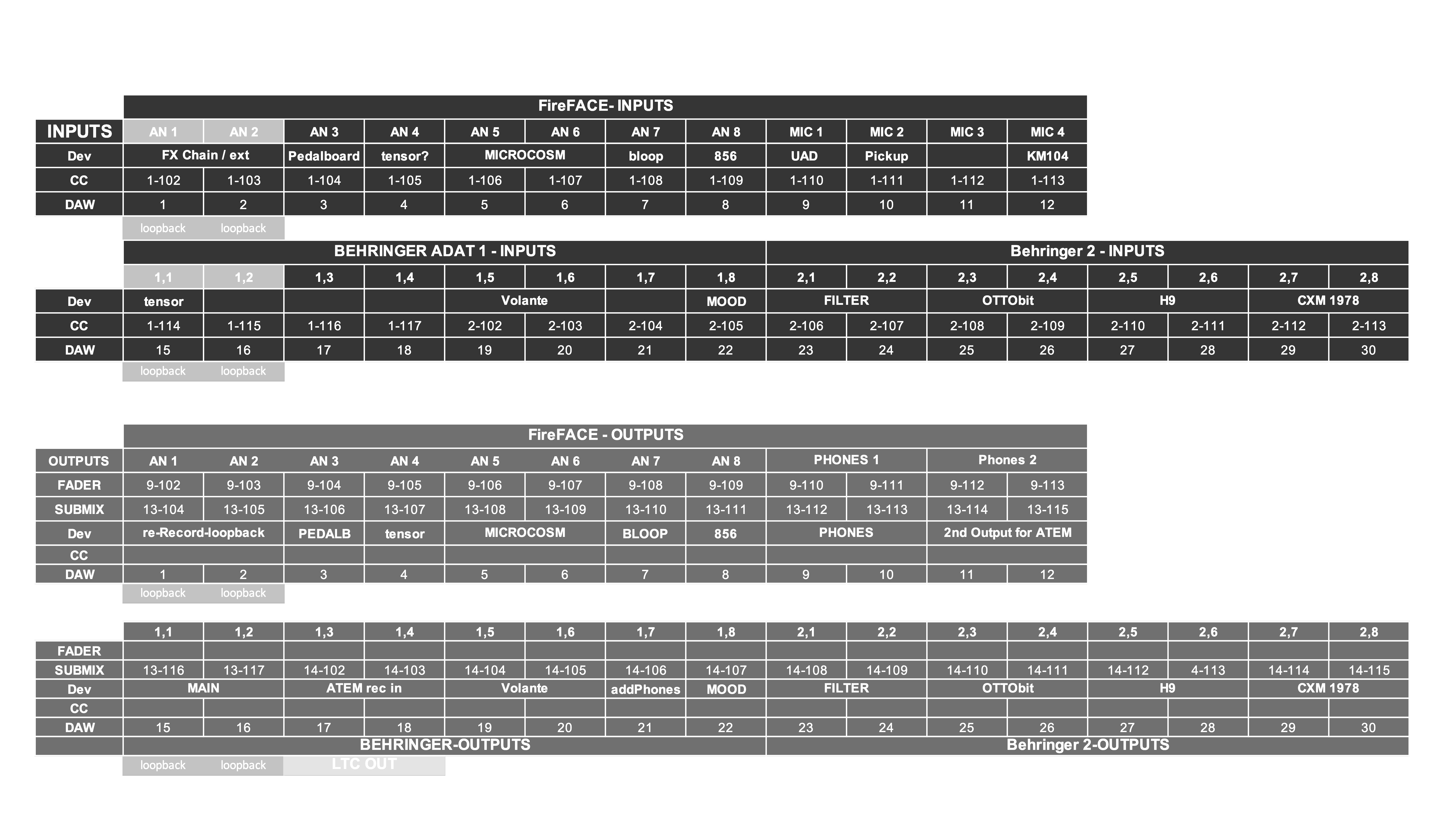
I then made an overview with all my used inputs and outputs and the relevant midi commands:
How do I get the information of pressing a launchpad pad converted into midi and being sent to [RME Total MIX][totalmix]? How can I get a visual feedback? How can I store and recall settings?
How to store a matrix? (Python Lists)
I had to handle the information of which connections I make or which connections are active. I had to use the programming language Python to write custom functions inside ClyphX Pro. These are called user_actions.
There are many concepts to handle and store parameters in Python. A simple one is a list, where parameters are written one after each other, like this:
list=[value1, value2, value3, etc…]
To access position 3 you use
list[2]
In programming position 1 is referred as 0, also called the programmers 1.
To store the values of a 12×12 matrix, I needed 12*12 positions, 144 in total.
Back to my original concept I stored the data corresponding to this table:
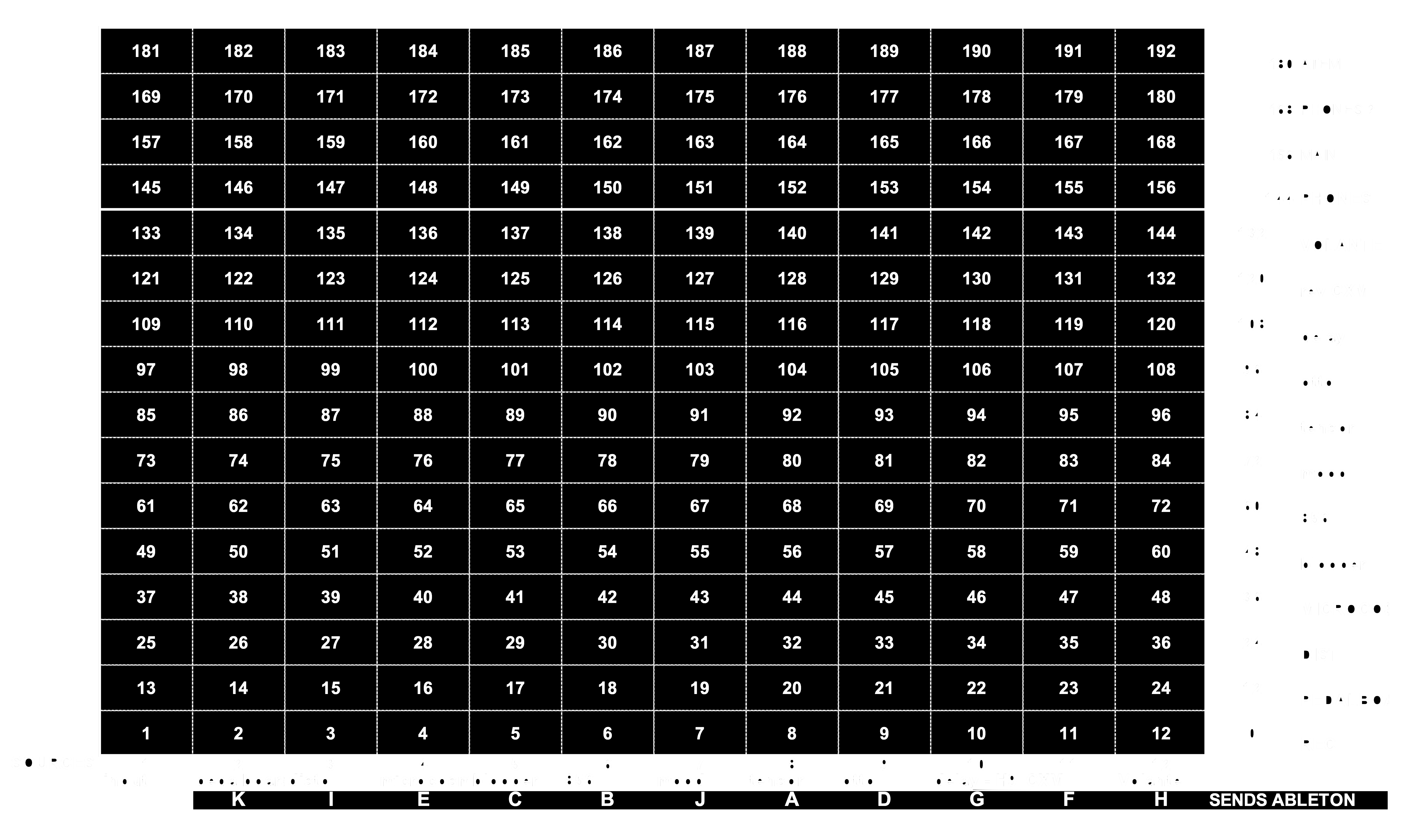
To give you an example: To access the value for the route:
source blooper → destination 856 it’s cell Nr. 65, the programming code would be: list[64]
I used 4 more outputs and wanted to store those values as well. Now it is a 16×12 matrix.
Limitations
This is a simple solution and it works, but it has limitations, which are bothering me:
fixed size
It is not expandable. When I would add another input it would be a 16×13 matrix and all cells would be renumbered. I would have to re-write all of my programming code.
readability
When using this list, it is not obvious what number 152 stands for. There are solutions in Python which would look like this:
list[source:tensor,submix:phones1]=XX
Here it is readable which cell 152 stands for.
Or if I use a two dimensional array(you can think of it as a table with rows and columns) it wold look like this:
list[7][12]=XX
7 is the column 8 of the sources (tensor) and 12 is row 13 of the submixes (phones1) when you look at the table above. 152 = 8 + (12*12). 12 multiplied for each row.
Future plans
The re-programming of my matrix structure is right on the top of the list of my Future Plans. But it also means I have to reprogram most of my functions, which I don’t have the time now.
connecting the dots
I now know what MIDI commands I have to use, how to store parameters and what hardware controller I want to use. Time to bring all pieces together.
ClyphX Pro, matrix launchpad and MIDI
I used ClyphX Pro to configure my launchpad mini mk3 to send the right midi data. In ClyphX Pro there is a simple action to generate MIDI data.
MIDI CC CHANNEL NR VALUE
For each submix I defined a MACRO:
$SUBMIX-TENSOR$ = MIDI CC 13 107 127;
To program the button for selecting the submix for the tensor I define a G-CONTROL on my launchpad with an event for pressing and releasing the pad:
B_2_23 = NOTE, 4, 22, 0, 127, FALSE

B_2_23 PRESSED = MSG "SUBMIX TENSOR"; $SUBMIX-TENSOR$;

B_2_23 RELEASED = MSG "SUBMIX PHONES"; $SUBMIX-PHONES$;
I did a similar thing for the source buttons. When I release the destination button it snaps back to the phones mix. Doing it like this I am forced to actively choose which destination and would not make any connection to a previous selected submix by accident.
The MIDI data is sent to the MIDI output defined for ClyphX Pro in ABLETON LIVE MIDI PREFERENCES. I use a virtual MIDI device. This is a built-in feature of MAC OSX. In this way I can redirect a MIDI signal from one application to another internally:
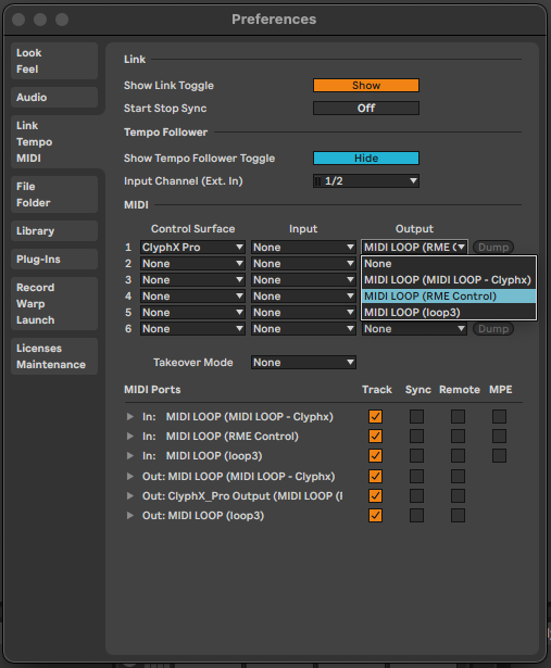
I had to overcome various difficulties during the programming. It is not possible to set a variable from inside a macro in ClyphX Pro. But this was essential to make my concept work. To store the volume value into my list, I had to set a variable to tell ClyphX Pro which submix(row) I pressed in the first place. Only like this I could address the right position in my list.
I ended up writing my first useraction setvar to override the limitation from within macros. I published the action on the forum and it is used by many from the community now.
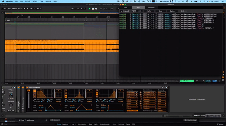
Visual feedback
For an intuitive operation I needed visual representation of what is going on inside the matrix. I came up with this solution:
When selecting a submix, the active sources(pads) started to blink on the left side on my launchpad source section. I did this with a user action matrixstate.
Inside ABLETON LIVE I have a MIDI track assigned to the LAUNCHPAD with a MIDI CLIP running in a loop. If you send a MIDI note the corresponding pad will light up. The useraction reads out the submix row of my matrix and turns on or off the right MIDI notes. When releasing the submix button, all MIDI notes from the Phones submix get activated again.
This useraction does give date for OSC output as well. On my iPad I have a dedicated page where I can see all active routes at a glance.

I found this view not that very helpful as it is too cluttered for my taste. I have ideas how to do this properly in my FUTURE PLANS
SNAPSHOTS
When jamming I missed the possibility to store the state of my matrix to be able to recall it later. I was able to write a store and recall user action, although it does not work perfectly yet. I store the matrix-list in a dedicated clip name. Weirdly enough clip names in ABLETON LIVE are a great container for information as they seem not limited to a small length.
Meanwhile, I do use more than 12 sources, (MIC1, MIC2, MIC3 etc…). This is perfectly fine when it comes to control Totalmix, but the stored list inside my setup can’t hold all of the data, as I mentioned earlier when I wrote about limitations.
As time is running out at the moment, this is also on my list of FUTURE PLANS
Further aspects of audio signal routing
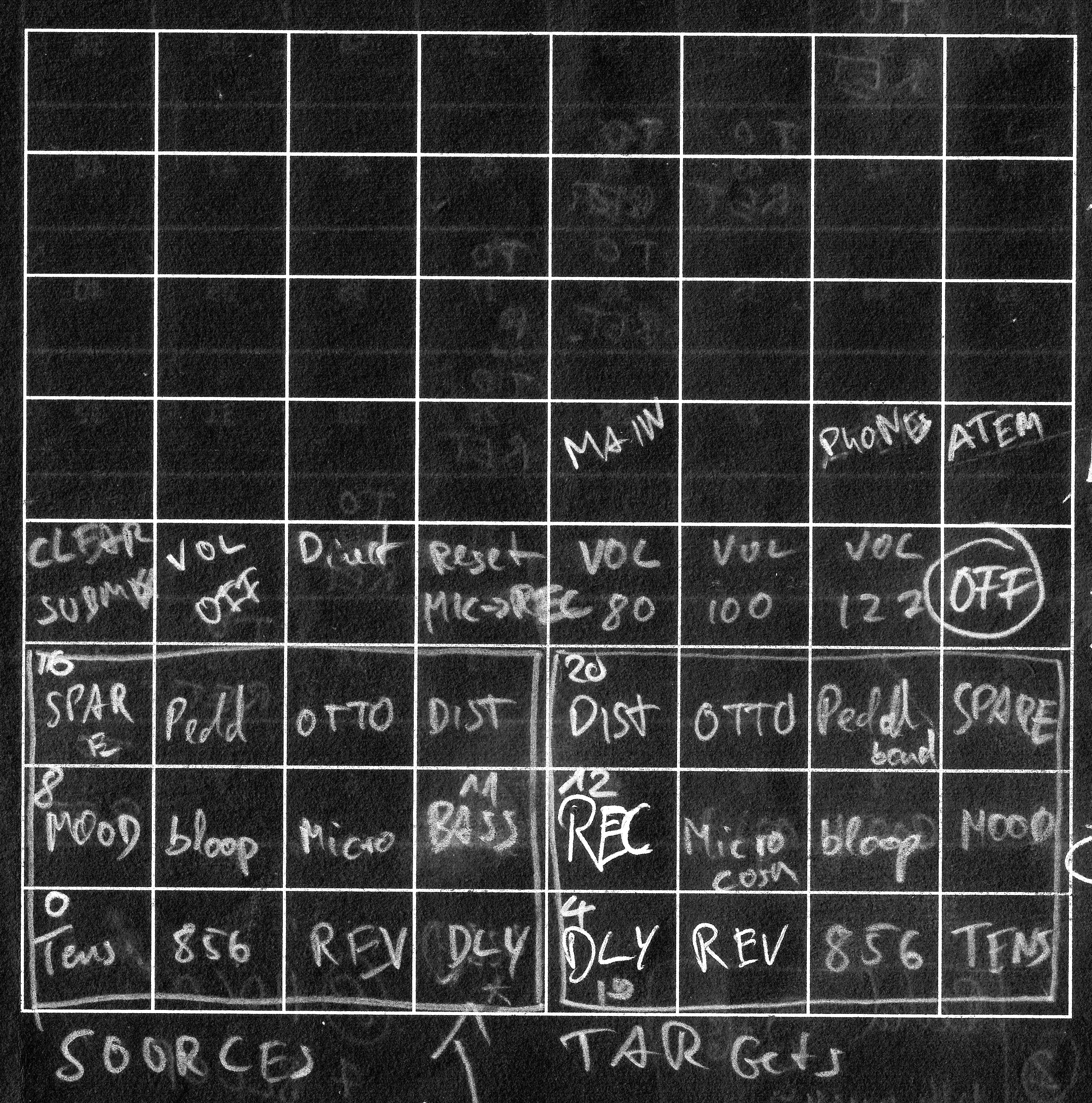
While developing early versions of the matrix, I wrote down my concepts of possible and relevant signal routings. After using my setup it for a while it became clear I want to have a flexible monitoring/recording routing:
This is a rough schematic of the most needed signal routings:
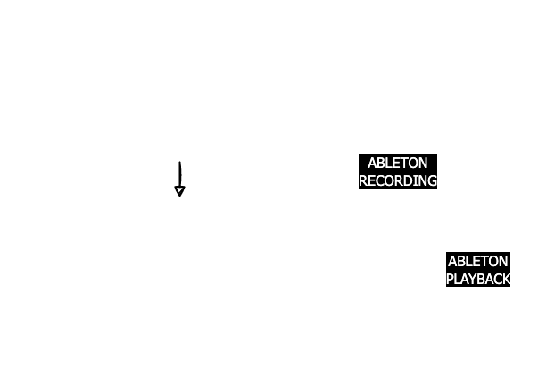
I break them down to two types of recording and playback. Wet and dry. Wet/dry is not a standardised term, but it means dry→ without effects, wet→ with effects.
DRY / WET
DRY RECORDING
For a dry recording scenario I would like to hear my signal with effects, but record the dry signal. With this procedure I am able to tweak effects after recording. This is useful with effects like e.g. delay or reverb. With a short loop the effect is “longer” than the loop itself.
WET RECORDING
In a wet recording scenario I want to record the signal with the effects “burnt in”. This could be helpful when the effects like stutter, distortion or modulation. When recorded like this the effects would be “free” for other uses after recording:
DRY PLAYBACK
When audio is played back, it is routed directly to the output, without any effects added to it. This is normally used when it was recorded wet.
WET PLAYBACK
This is normally used when a loop was recorded dry. The audio goes into my mixer matrix gets treated with effects and is finally routed to the output.
ANYTHING AND EVERYTHING IN BETWEEN
Now, it can be a mixture of both. e.g. the bass is recorded with a pitch shift and distortion, but goes into a delay afterwards which is not recorded and can be manipulated later during playback. Everything is possible and easy to dial in. But it is dangerous territory, it easily gets complex and hard to control. On the other hand it is a land full of lucky accidents and surprises. A creative wonderland to get lost. But also a possible waste of time and swamps of unpleasant noise. But this is in the nature of taking creative risks, I guess.
seamless from dry recording to wet playback
A challenge I encountered while realising this setup was having a seamless transition between recording dry(while playing bass with effects) and playing back through the wet signal chain.
All the schematics above are a simplified version. I use a submix of [RME Total MIX][totalmix] as a recording bus for ABLETON. I use the loopback feature which sends the audio from an output back to the software input. This is useful if you want to record a submix. In my case I have the same hardware input inside ABLETON LIVE and therefor minimal CPU strain. Plus, I am flexible to route any combination of hardware input to the recording bus inside [RME Total MIX][totalmix].
Inside ABLETON LIVE I have for each effect an independent send. I had to “clone” the routing of [RME Total MIX][totalmix] and apply it to the sends of the loop audio track inside ABLETON.
I realised this with a user action montosends which means “copy monitor to sends”. This reads the recording bus row of my matrix and pastes the corresponding values onto the desired loop track sends in ABLETON.
I also wrote a user action to apply the wet recording scenario. The user action is called montorec and stands for “monitor to recording bus”. It clones the phones submix to the recording bus.
There is a built-in function in [RME Total MIX][totalmix] which does exactly that. But unfortunately it is only accessible through a context menu when right clicking the mouse on a submix. I wrote to RME many times to make this functionality available via MIDI, but I’m afraid I am the only person who is interested in that.
SUMMARY
The realisation of my idea of a flexible mixer matrix was very intense, but I am confident that it works rock solid and can be developed further. The possibilities
to combine external effects and control the signal flow from ABLETON pre-scripted are endless. Thanks to the stability of [RME Total MIX][totalmix] my setup is reliable and responsive. It feels like an instrument. Everytime I start making music with it I feel satisfied, because it is just a millisecond from that moment of “How would it sound if I send this there and then back to this pedal” to its realisation.
It was worth all the effort and I do not regret having chosen the red pill.
See you on the other side…..
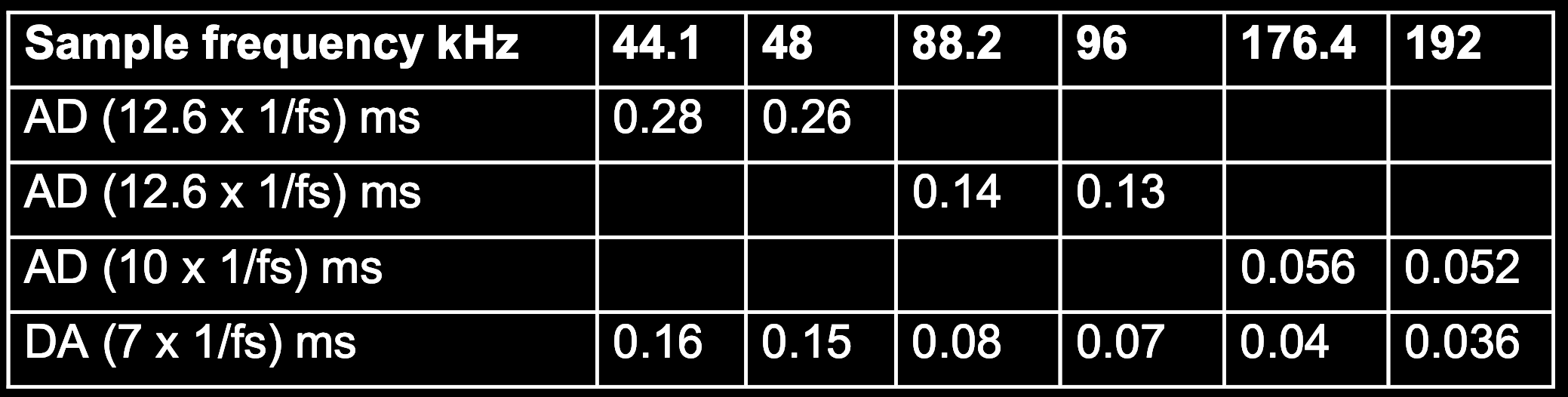
- EXCERPT of the manual of the Fireface 802 in regards to Zero Latency Monitoring(page 101):
37.2 Latency and Monitoring
The term Zero Latency Monitoring has been introduced by RME in 1998 for the DIGI96 series of audio cards. It stands for the ability to pass-through the computer’s input signal at the inter- face directly to the output. Since then, the idea behind has become one of the most important features of modern hard disk recording. In the year 2000, RME published two ground-breaking Tech Infos on the topics Low Latency Background, which are still up-to-date: Monitoring, ZLM and ASIO, and Buffer and Latency Jitter, both found on the RME website.
How much Zero is Zero?
From a technical view there is no zero. Even the analog pass-through is subject to phase er- rors, equalling a delay between input and output. However, delays below certain values can subjectively be claimed to be a zero-latency. This applies to analog routing and mixing, and in our opinion also to RME’s Zero Latency Monitoring. The term describes the digital path of the audio data from the input of the interface to its output. The digital receiver of the Fireface 802 can’t operate un-buffered, and together with TotalMix and the output via the transmitter, it causes a typical delay of 3 samples. At 44.1 kHz this equals about 68 μs (0.000068 s), at 192 kHz only 15 μs. The delay is valid for ADAT and SPDIF in the same way.
Oversampling
While the delays of digital interfaces can be disregarded altogether, the analog inputs and out- puts do cause a significant delay. Modern converter chips operate with 64 or 128 times over- sampling plus digital filtering, in order to move the error-prone analog filters away from the au- dible frequency range as far as possible. This typically generates a delay of one millisecond. A playback and re-record of the same signal via DA and AD (loopback) then causes an offset of the newly recorded track of about 2 ms.
Low Latency!
The Fireface 802 uses AD and DA converters with an innovative digital filter, causing a delay of only a few samples. With 12 samples AD and 7 samples DA the delay caused by the conver- sion is only about a quarter of previous generations. The exact delays of the Fireface 802 are:
 ↩︎
↩︎